HVAC-R system integrator

Transferring technology into performance

Do you have any questions?

Or would you like to know where to find us? Please feel free to contact us.
Concept Studies
Investigating & analyzing different design options to detect constraints and optimize the solutions before basic and detail design.
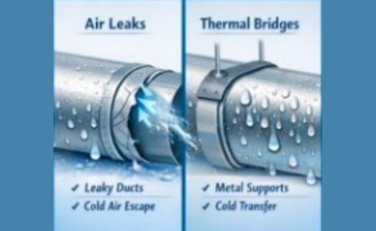
Evaluate the risk of condensation and finding the most cost efficient and optimal solution to avoid it.

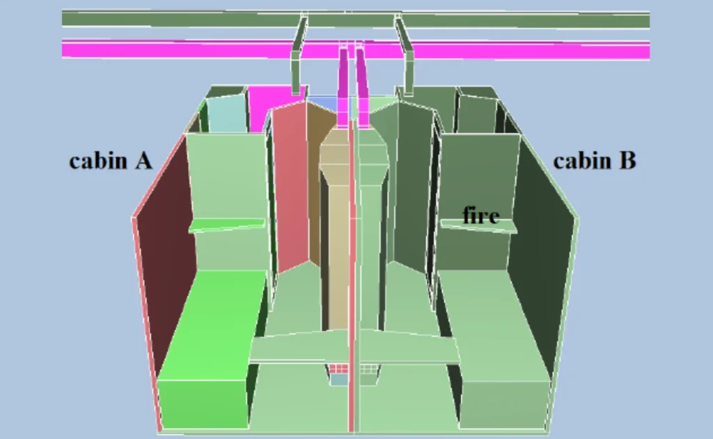
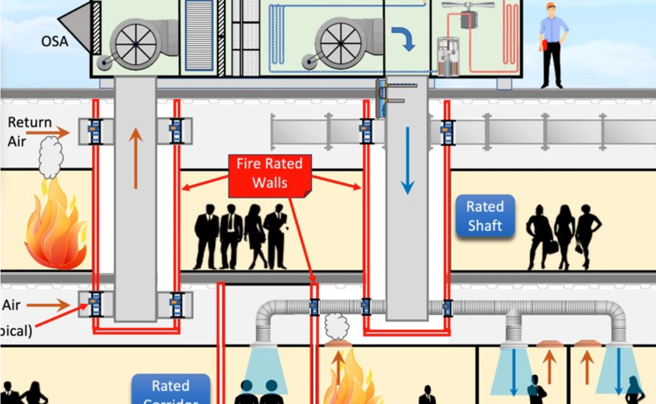
Study to investigate the risk of fire in one room might cause smoke to spread through the ventilation system and into other rooms.

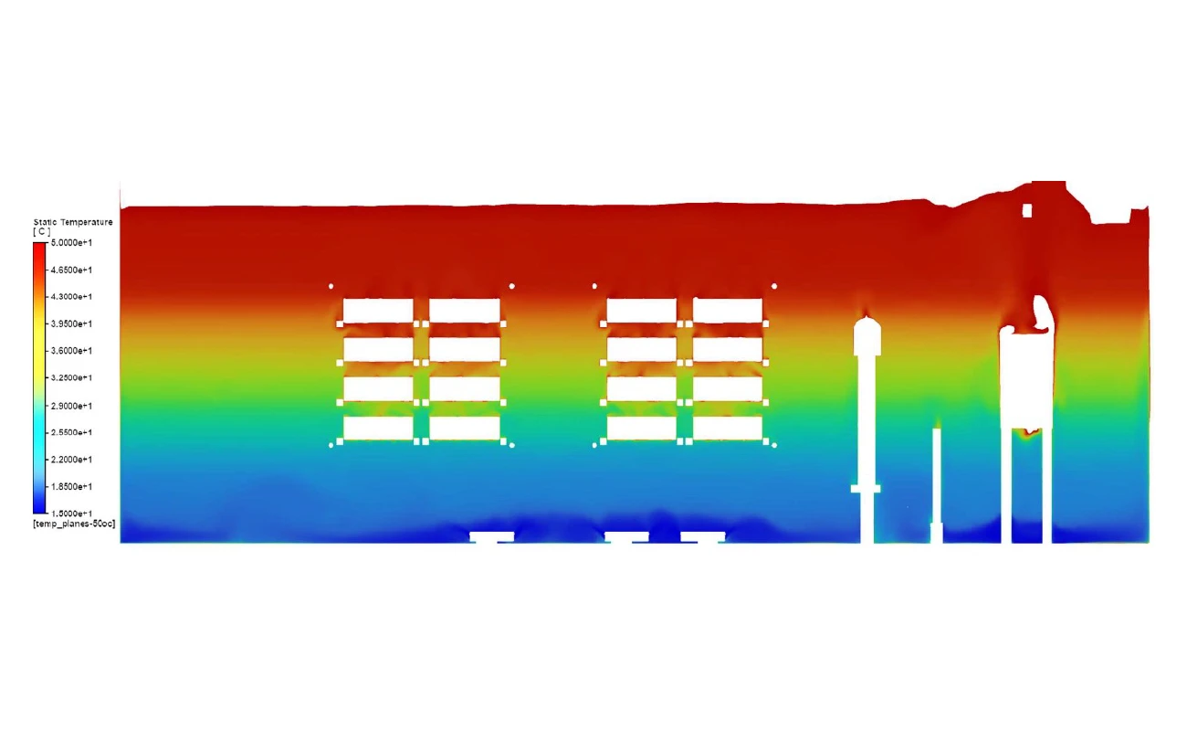
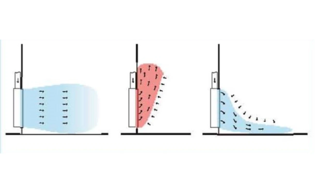
Computational Fluid Dynamics (CFD) calculations to analyze and evaluate the effectiveness of the design solutions given in the detailed design phase with regards to temperature stratification, hot air pockets and avoid areas with critically high temperatures.

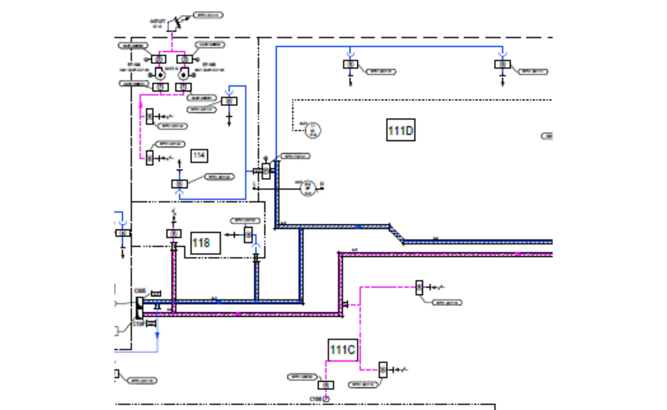
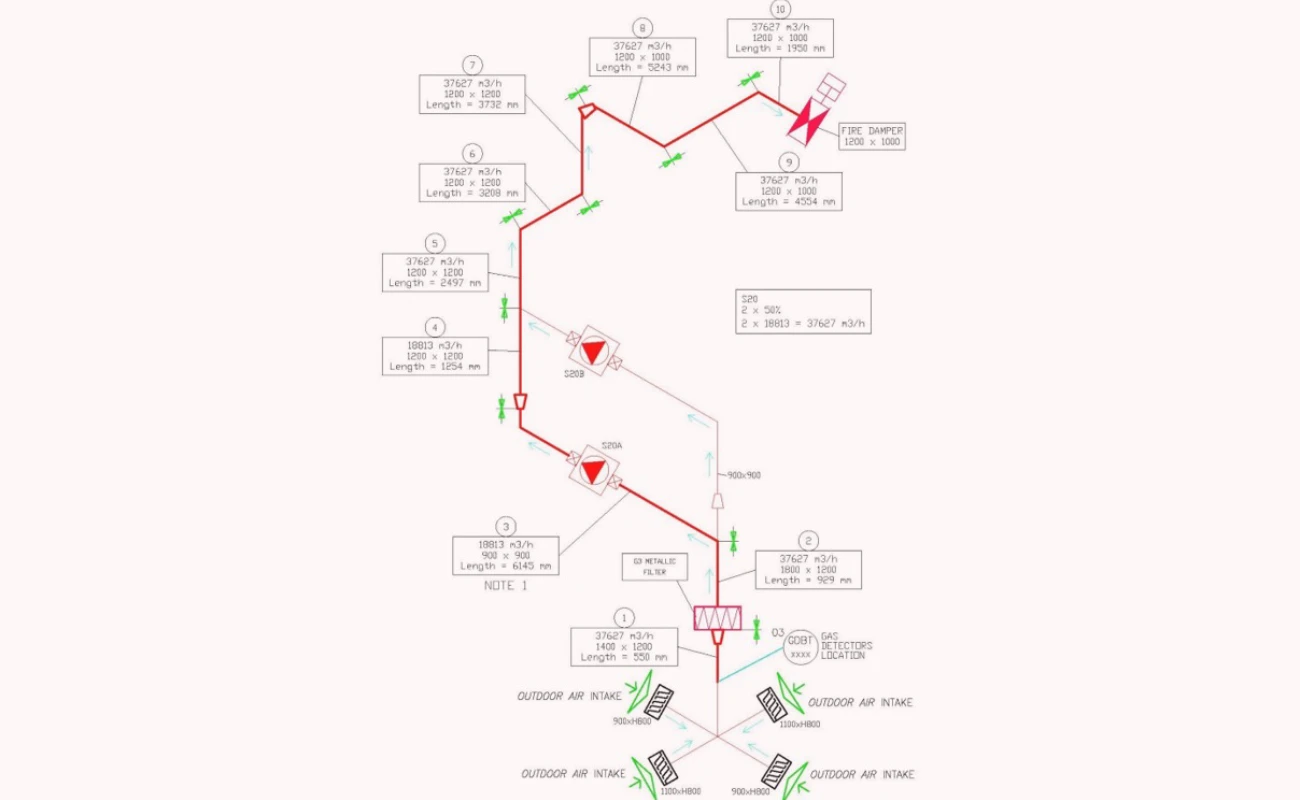
Calculation of Heating, Cooling and Airflow requirements, production of Airflow Diagrams, Cooling Medium Diagrams, Control Diagrams, D&IDs, P&IDs, Basic Philosophies, Equipment Lists, Data Sheets, GA-drawings, and other Basic Design documents. Selection of equipment is part of this stage.

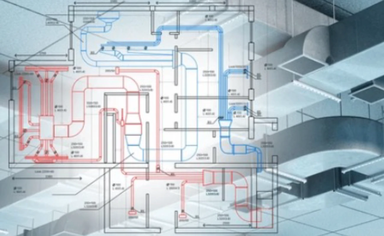
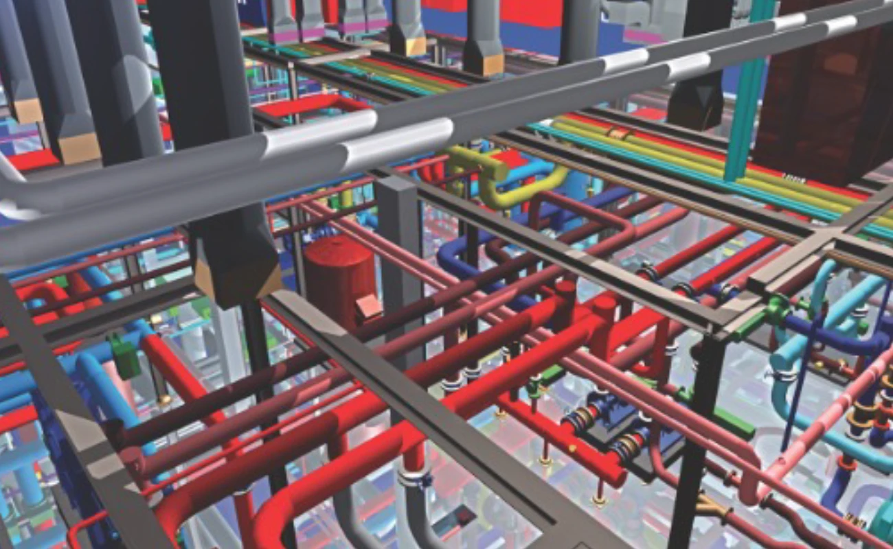
Single Line Diagrams, Control Philosophies, Pressure Drop Calculations, Noise Calculations, Load Lists, Signal Lists, Instrument Lists, Equipment Foundation Drawings, and other Detail Design documents. Detail duct routing and design as well as verification and adjustment of equipment selection follows the detail design development.

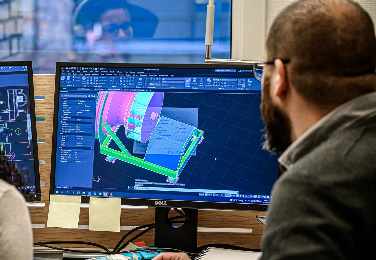
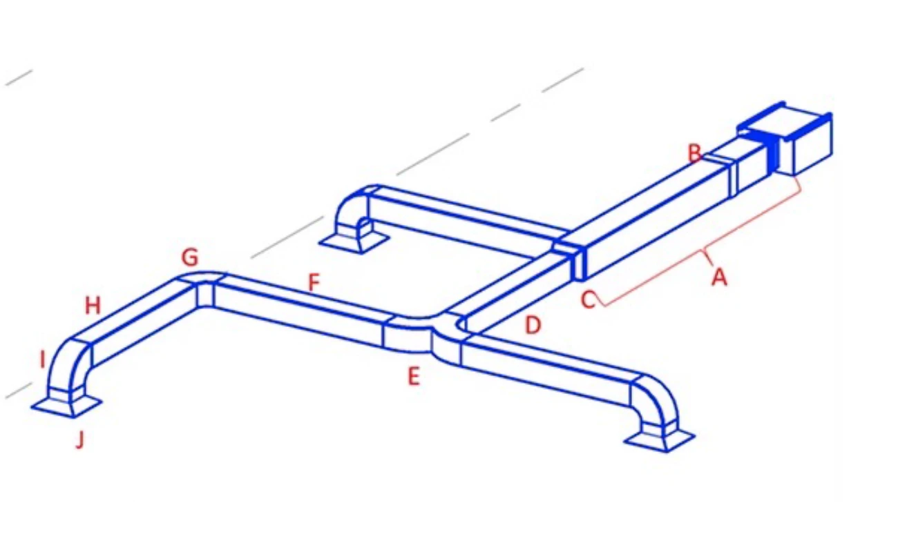
Computer Assisted Design for duct layout, pressure and noise calculations.
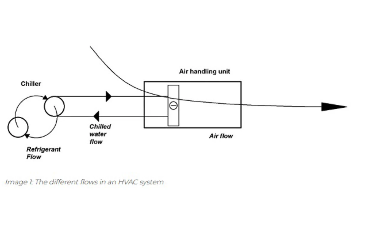
Knowing the installation’s total cooling requirement and the project’s specifications enable the optimal selection of solution and design of the cooling system.
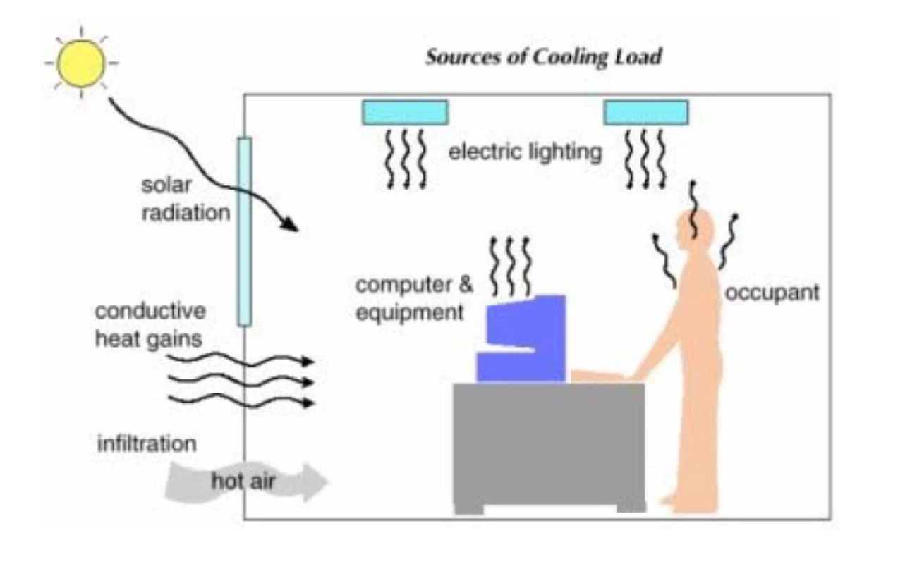
Knowing the meteorological conditions on site, properties of the construction, internal processes and heat loads, enable an accurate calculation of energy to be added or removed.

Knowing the heat gains and losses, the specified internal conditions, fresh air requirements, minimum air changes and other special requirements enable the calculation of the required supply air.

After duct layout and sizing is done, and equipment is selected, the pressure loss calculations will be done to verify the performance of the system, and if required detect the need for minor modifications to optimize the system.
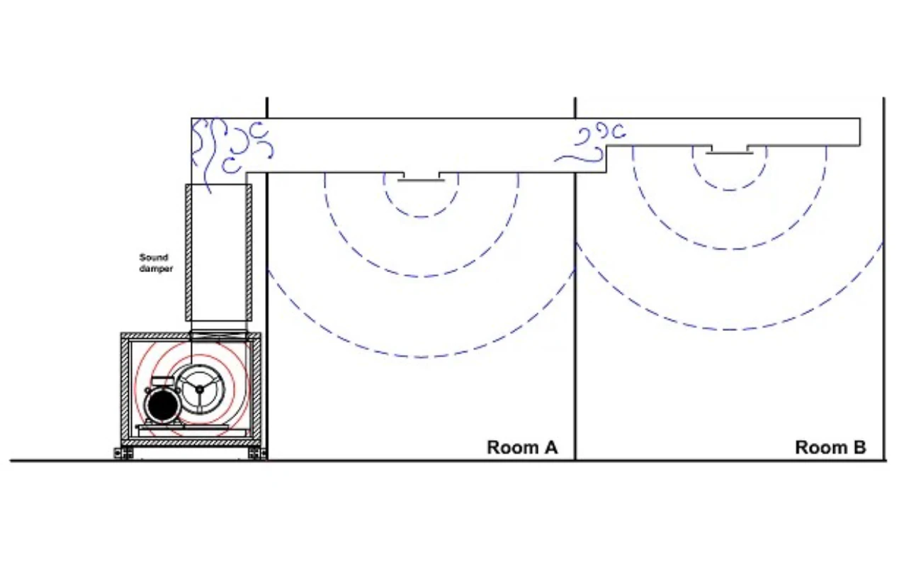
The Noise Calculations will be done after the Pressure Loss Calculations to verify the noise levels generated from the HVAC System. This will reveal potential requirements for sound attenuators or other measures to be taken to comply with the projects noise limits.

The outdoor air intake ducts shall be designed to prevent any smoke or gas from reaching ventilated areas where it can cause hazard to people/equipment or ignition sources. The calculations will take into consideration F&G response time to close the relevant fire/gas damper.

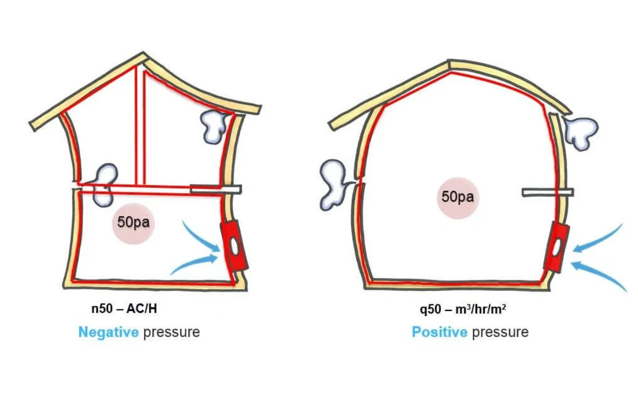
The difference of supply air and extract air is loss of energy. If required we calculate the leakage rate of the ducting and building to find expected leakage, hence the required spare to be added on the supply air.

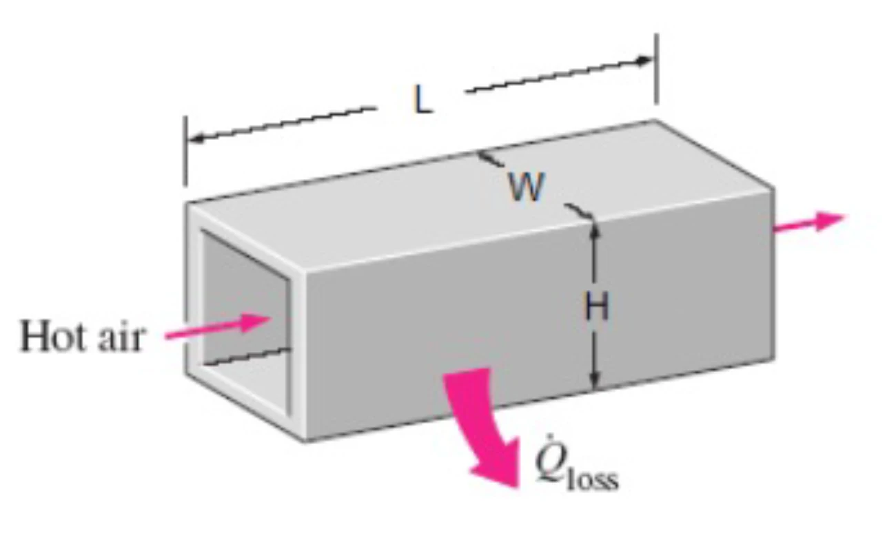
In special situations the calculation heat loss from ducts during WINTER and heat gains from ducts during SUMMER might be required to determine the necessary duct thermal insulation thickness or to design the right supply temperature. Thermal insulation of the supply ducts contributes to an effective HVAC System, by reducing the energy needed to maintain the correct SUPPLY AIR temperature to the rooms, as well as minimizing the risk of condensation.

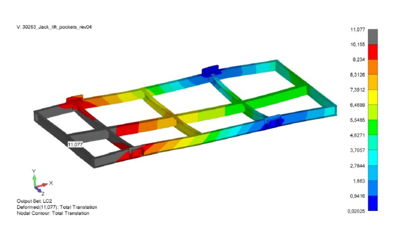
Strength calculation of HVAC equipment, base frames, or lifting appliances is sometimes mandatory to ensure a safe and durable installation.

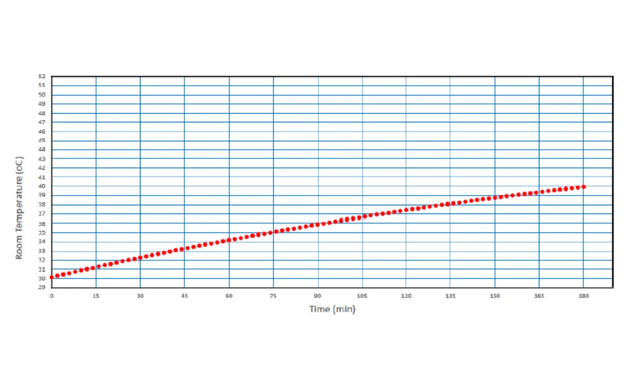
The UPS (Uninterruptible Power Supply) rooms are typically rooms containing batteries designed to provide emergency backup electricity instantly if the main utility power fails. For this reason, calculations are sometimes done to verify how long it takes after loss of the main electricity before the rooms reach a critical temperature.

The HVAC system is an important part of the overall Fire & Gas system of an installation. It contributes to a safe and continuous operation of the installation. The basic rules are based on either national or international regulations in addition to IMO or company philosophies. Fulfilling applicable rules and regulations include correct application of fire dampers, duct classes, as well as complying to design and operational philosophies.

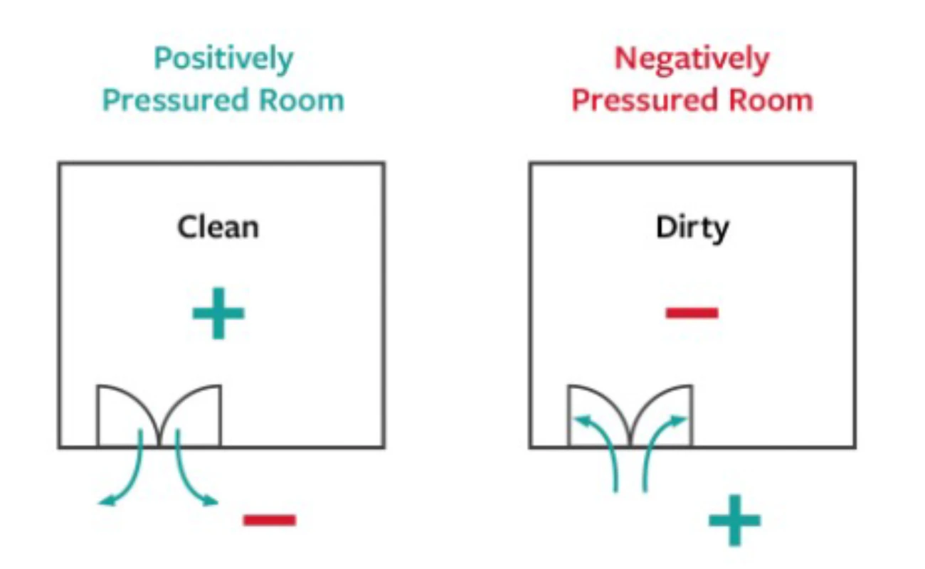
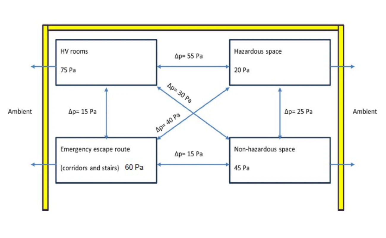
Design with under- or overpressure of the different rooms to either prevent spreading of hazardous or contaminated air, or to prevent ingress from adjacent rooms.
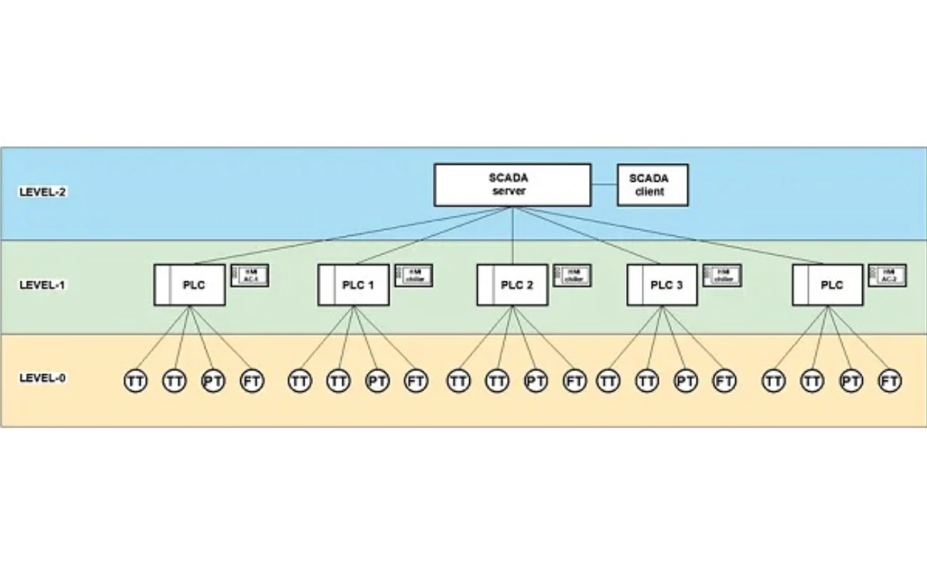
The final step to ensure a safe, optimal, and well-functioning HVAC system is to make all the pieces work together as intended by providing a tailormade control system. In this phase we typically make Functional Descriptions, Loop Diagrams, Wiring Diagrams, Termination Drawings, Electrical Block Diagrams, Control Narratives, and Cyber Security Procedures.


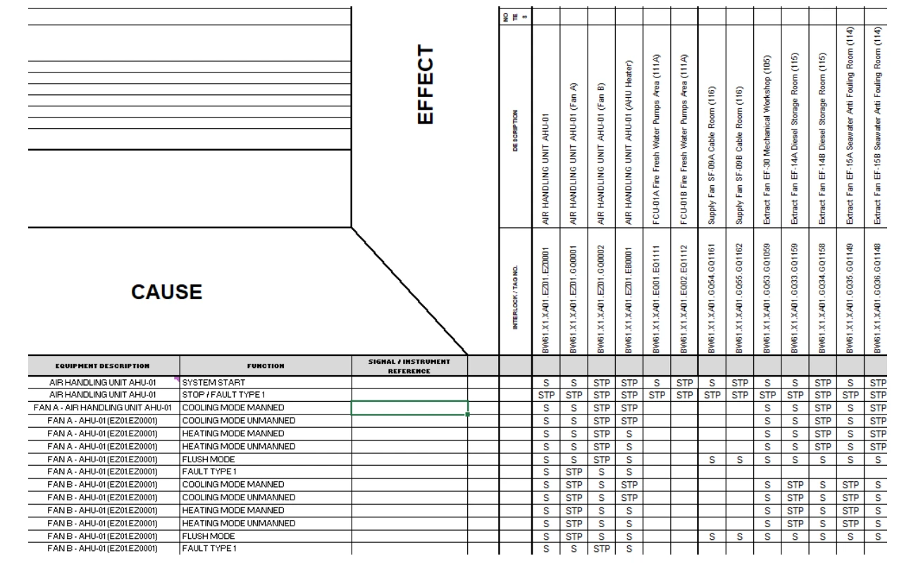
The target is always to keep as many rooms as possible operable but at the same time ensure safety for people and equipment. However, in some unwanted situations as a fire, smoke development or malfunction of safety equipment it might be required to shut down certain areas of the installation. This is often described in the Fire- and Safety Philosophy and might require specific actions to be taken for part of the installed equipment. It might include closing fire dampers, stopping AHUs/fans or other equipment, and sometimes starting smoke extract fans. This will typically be reflected in a Cause & Effect diagram.